Metalic Expansion Bellow
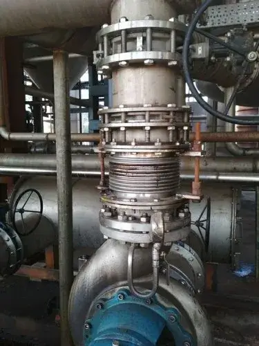
Single or Axial Expansion Bellow
Axial expansion metal bellows should be installed co-axially with the pipes centreline. The purpose of this bellows is to compensate axial movements. With the existence of axial movements desired cyclic life can be achieved. If incase there exist other movements like angular or lateral this will affect the cyclic life of Bellows. Generally there expansion joints are used between straight pipes where movement is parallel to the centreline of pipe line.
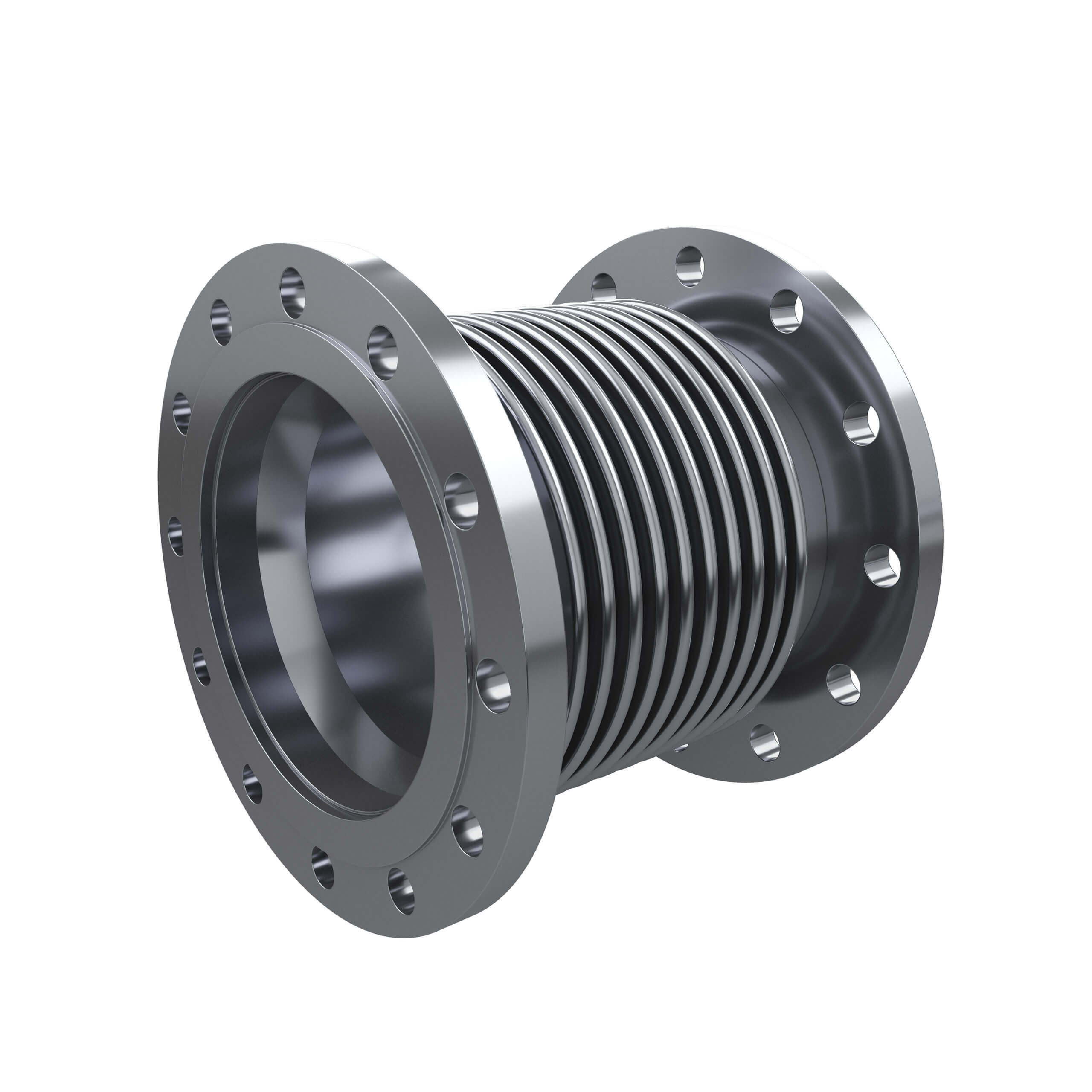
Use These Bellows In Following Circumstances
- Movement compensation is in straight line.
- Minute lateral/Angular movement can be adjusted but will affect the cyclic life of the expansion joint.
- Bellows are not designed to absorb rotary movements.
- Due to the line pressure between the piping systems numbers of expansion joints are required.
- The best piping system is the once which is broken between intermediate stages with metal bellows at each stage
Lateral Expansion Bellow
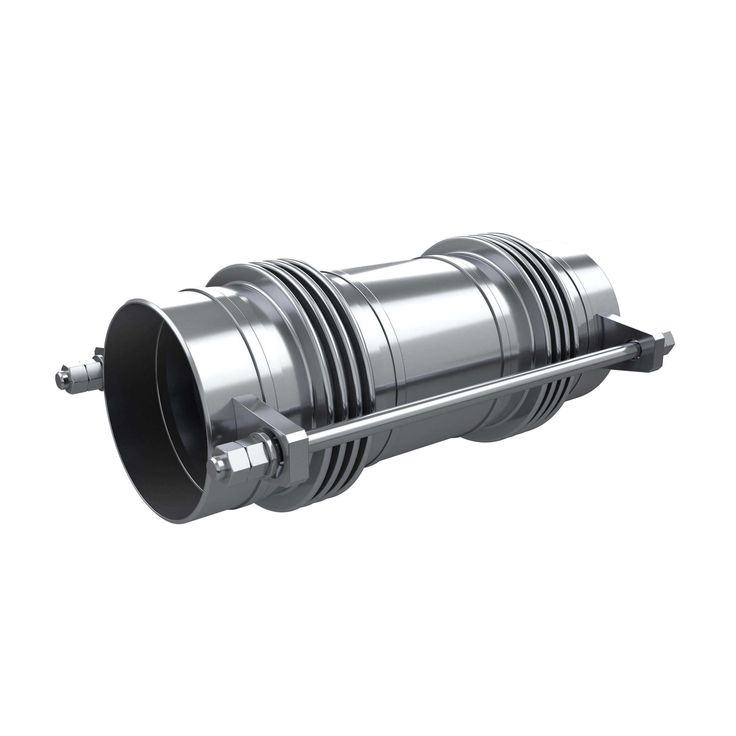
Lateral expansion joints refer to the direction perpendicular to the centreline of the pipe expansion joint. Lateral deflection is also called as PARALLEL OFFSET and TRANSVERCE. The lateral expansion joint are also known as Tied Lateral expansion joints or Tied universal expansion joints.
Incase of absorbing large amount of Lateral deflections universal expansion joints 2 bellows are connected by a centre spool (piece of pipe) and the tie rods are then attached on the outer ends for maximum deflection absorption. The length of centre spool (centre piece) plays a major role. In case the weight of centre spool is significant it is supported by lugs. The benefit of the Tied universal expansion joint is it can be used in place where the piping joints are not in one place.
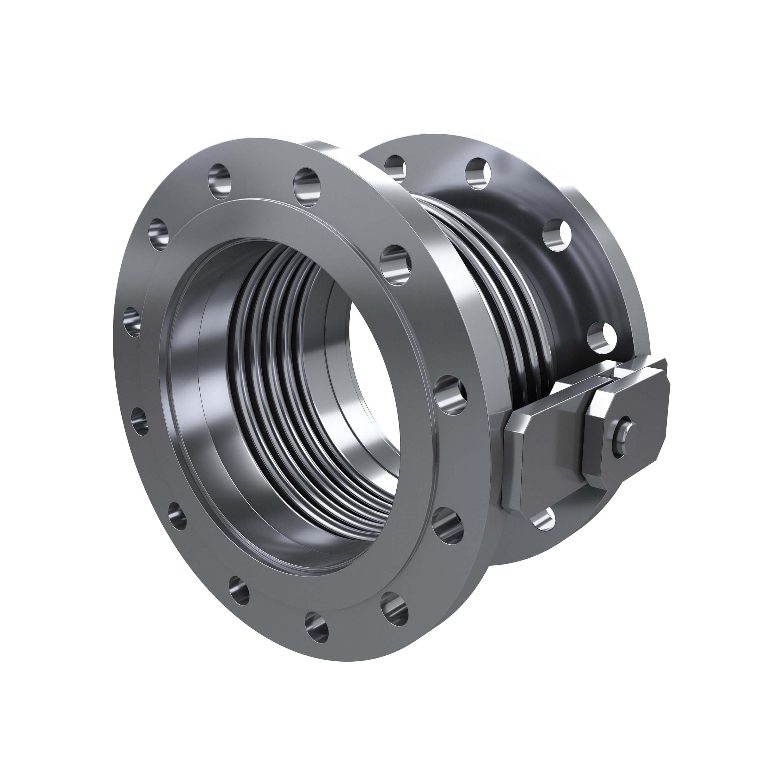
Hinged Expansion Bellow
When the angular movement is only in one plane hinge or angular expansion joints are used. An angular expansion can be expressed when an expansion joint experience bending about its centre which is the centreline and half way between the ends of metal bellows.
These types of bellows are used mostly in sets wherever piping direction changes. So you will find hinged joints used at the locations where pipe bending occurs. Due to the hinged nature of this bellow only angular movement is allowed around the hinges. Since lateral movements too take place so there is a piping joint between these 2 bellows. The amount of lateral deflection a hinged expansion joint can accommodate for a given angular movement is directly proportional to the distance between them. To use a pair of hinged bellows effectively the distance between them should be made as large as possible. When only two hinge joints are used as shown in the adjacent figure the piping perpendicular to the hinge segment must deflect to absorb the thermal expansion of the spool containing these angular expansion joints.
When the piping in a single plane system is not flexible enough to absorb the thermal expansion of the spool between the hinged joints a system of three hinged expansion joints may be used. In this system the combination of the three joints absorbs all the thermal expansion of the piping system and no deflection of the piping is observed. This system produces the lowest possible forces on the intermediate anchors and guides
If the thermal growth in the Piping System occurs in only one plane the use of this joint provides the most efficient solution to absorb the thermal deflections.
Gimbal Expansion Bellow
The gimbal expansion joint is the most reliable expansion joint since it is capable of absorbing angular motion in all the planes. Although single gimbal bellows joint can be used in isolation the most common applications use a pair of gimbal bellows joints to absorb a complex multi-plane motion in a piping system. In adjacent figure Gimbal Expansion Joints are utilized in a pair to absorb the thermal expansion from the two horizontal piping arms. However note that the thermal growth of the vertical.
To avoid this deflection in the horizontal piping arms one or more hinged expansion joints can be installed in the horizontal arms of the piping system.
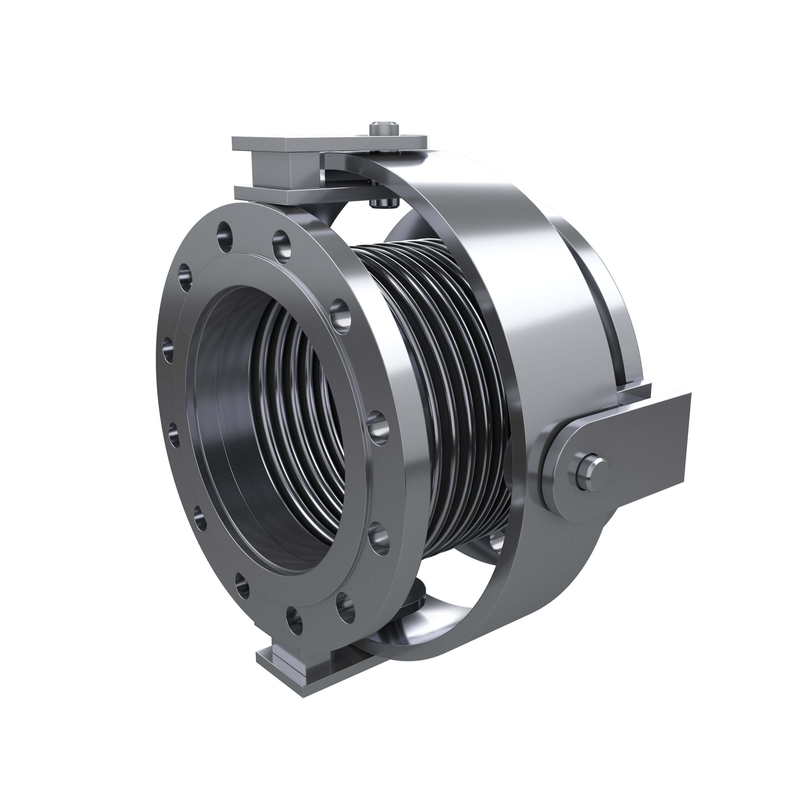
Pressure Balanced Expansion Bellow
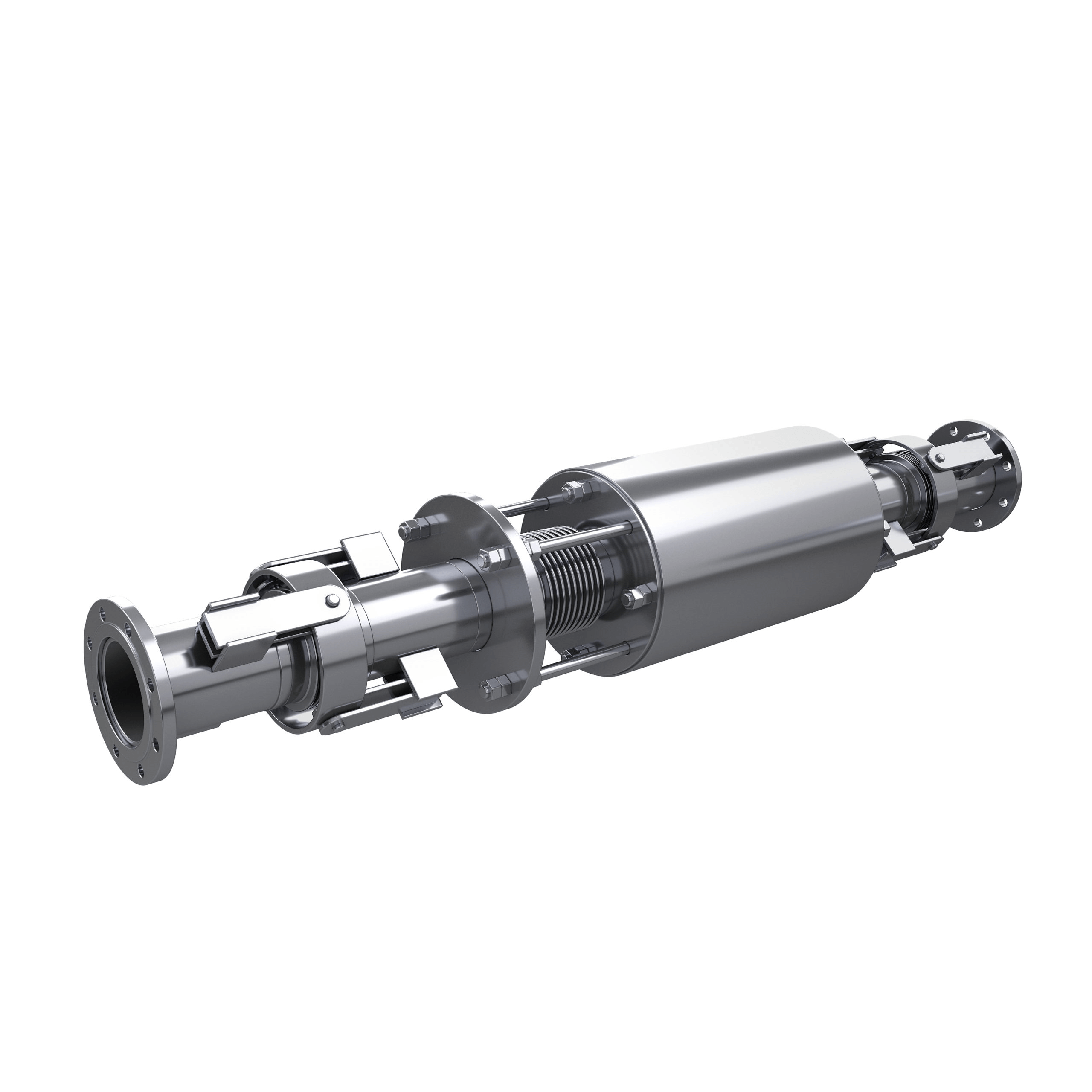
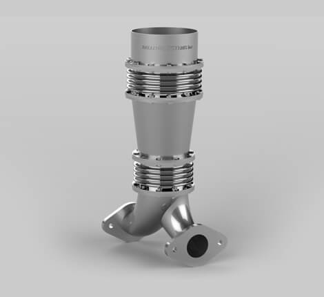
A Pressure Balanced Expansion Joint provides another method by which it is possible to eliminate pressure thrust, reduce anchor loads, and make possible the relocation of an anchor at a more accessible and advantageous position. Pressure Balanced Expansion Joints are particularly well suited to applications involving rotating machinery such as turbines and pumps, where it is desirable to reduce pressure thrust and, external loadings on equipment to minimums. The pressure balanced expansion joint can be either inline type or elbow type. The use of an Elbow type Pressure Balanced Expansion Joint necessitates a change in the direction of the piping.
In many applications, some lateral deflection is present on the line side of a Pressure Balanced Expansion Joint. Where the magnitude of the combined axial and lateral movement exceeds that which a single bellows can absorb, it is necessary to equip the line side of a Pressure Balanced Expansion Joint with two bellows. The balancing side requires only enough corrugations to compensate for the axial displacement. To compute the force to deflect this type of Pressure Balanced Expansion Joint, add to the total forces outlined above, the force to deflect the unit laterally.
Alternately, an inline pressure balanced expansion joint can be used when axial deflection is present and anchoring is not a suitable option. The operating principle is the same as the elbow type expansion joint, with an intermediate bellows with large thrust area is used to absorb the thrust pressure loads from the inline Bellows.
Rectangular Expansion Bellow
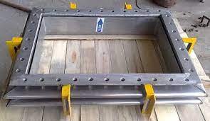
Bellows Systems manufactures Rectangular Expansion Joints to absorb thermal movements and vibration in either square or rectangular ducting in applications such as turbine condensers. Most Rectangular Expansion Joints are custom designed for specific design and service conditions depending on the application.
Bellows Systems Rectangular Expansion Joints are made “V” shape convolution profile and available in single or double miter and camera corner configurations. “U” shape convolution profile with rounded corner configuration is also available in limited sizes.
Rectangular metal pipe expansion joints have a variety of applications in the power, petrochemical, refining, chemical, and steel industries. Like circular pipe expansion joints, rectangular pipe expansion joints absorb three types of movement: axial, lateral and angular. For the purpose of designing rectangular bellows, it is critical to know in which direction the lateral and angular movements will occur, i.e. parallel to the long and/or short side of the bellows. Unlike circular bellows where the pressure stress is a circumferential membrane (hoop) stress, the rectangular bellows must be designed for longitudinal (beam) bending stresses.
Thick Wall Expansion Joint
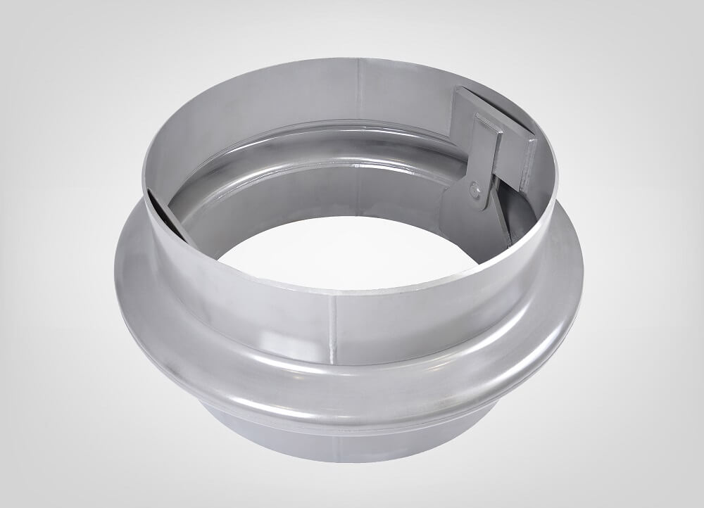
Thick Wall Expansion Joint designs are identified by a thick ply and high convolution height. They are typically used in heat exchanger applications. Thick wall expansion bellows are usually are manufactured in single convolution with one or more thick ply’s.
Bellows Systems designs both Lens Type and Flanged and Flued Type thick wall expansion joints. Flanged and Flued Expansion Joints typically have higher stiffness and absorb less axial deflection compared to lens type Thick Walled Expansion Joints.
Applicable design codes include ASME B&PV Code Sec. VIII Div-1, Appendix 5 ASME B&PV Code Sec. VIII Div-1 Appendix 26 and EJMA.The most common application for thicker wall/flanged and flued expansion joints is heat exchangers and large diameter piping systems.
Bellow Testing
Bellows are correlated with actual test results to demonstrate predictability of design parameters like rupture pressure, squirm and cycle life for a consistent series of bellows of same basic design.
Purpose of testing
To assure a purchaser (user) that the product has been properly designed and manufactured; which requires some method of examination and testing of the product. The user may specify the kind of test required in the acceptance criterion
Various testing being done as a part of bellow manufacturing were
- Pneumatic pressure tests
- Hydrostatic pressure test
- Visible Dye Penetrant Test
- Fluorescent Dye Penetrant Test
- Radiographic Tests
- Helium Leak Tests
Radiographic Tests
This method is based on the principle that extremely high frequency light waves, usually x rays will penetrate solid materials and, when projected on to photosensitive film, will reveal voids, areas of discontinuity, and lack of homogeneity. This examination is widely used to evaluate the soundness of welds. Unless required by the purchaser, radiographic examination of the longitudinal seam of a bellow need not be specified.
Fluorescent Dye Penetrant Test
This method consists of cleaning a surface, coating it with a dye which contains a fluorescentmaterial, wiping the dye off and coating the surface with a developer which after sufficient time will draw the dye from the cracks, pin holes, and make them apparent to the observer. Liquid penetrant examination is limited in the scope to detecting the surface defects
Helium Leak Tests
Pneumatic pressure (air) tests
Low pressure air tests utilizes a probe of suitable design which selectively indicates the presence of halogen gases.This examination is more sensitive than a hydrostatic test or air jet leak examination but since it is done at low pressure, it can only determine the presence of a leak and cannot validate the structural integrity of the item being examined.
